

ZED X One Core Interfaces
The ZED X One Core exposes all its signals on a single 30-pin Micro I-PEX connector located on the back of the module. This page describes that connector, its voltage levels, its pinout, and the I²C address map of the devices on the board.
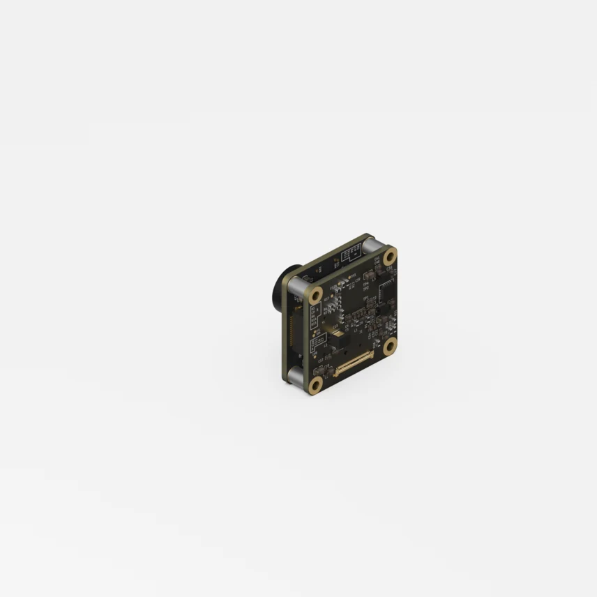
The information on this page is provided for mechanical and electrical integration purposes. The ZED X One Core is designed for exclusive use with the ZED Link MIPI capture card; connecting it to a third-party host is not supported. If you need to interface the camera with your own carrier board, please contact support@stereolabs.com.
Connector
Signal voltage levels
Pin description
Pins 28 to 30 must all be connected: they carry the 3.3 V supply in parallel to provide the required current capacity. The module draws 0.8 W (240 mA @ 3.3 VDC).
Multi-camera synchronization
The FSIN input (pin 12) is the frame-sync / external trigger signal. When several ZED X One Core cameras are driven from the same trigger source, their exposures are aligned at frame level with a precision of 15 µs, which is what makes multi-camera surround vision and stereo pairs usable for perception.
I²C address map
Notes on the addresses:
- AR0234 image sensor - the address can be reassigned by the driver to another value, through the internal registers of the sensor.
- BMI088 IMU - the two addresses are those of the accelerometer and of the gyroscope, which appear as two separate I²C devices. The driver can remap them through the device tree.
- EEPROM - usually read only once, at driver probe time, by opening each link one by one.