

Multi-camera setup
In this tutorial you will learn how to create a multi-camera configuration with ZED devices.
For a multi-camera configuration it is important to correctly identify each camera in the system by using its serial number and precisely set the position and the orientation of each of them with respect to a reference point.
A working example is available in the zed-ros2-examples GitHub repository.
The launch file explained
The example launch file zed_multi_camera.launch.py allows you to dynamically configure a robotics system equipped with multiple different models of ZED cameras.
The launch file starts one Robot State Publisher node that defines the position and orientation of each camera in the multi-camera system, one Robot State Publisher node for each camera that broadcasts all the static frames of the camera, and one ZED node for each camera of the system.
The number of ZED nodes to start is inferred from the size of the parameters passed to the launch file from the command line.
All the ZED nodes are loaded in the same ROS 2 container as components using ROS 2 Composition.
Do not use this launch file to record SVO files from several cameras at the same time. On NVIDIA® Jetson™, recording several cameras loaded in the same container can make the hardware encoder fail after a few minutes and stop all the cameras. To record SVO files, run each camera in its own container, as explained in Record and Replay Camera Data.
Launch parameters
cam_names: (REQUIRED) An array containing the name of the cameras, e.g.'[zed_front,zed_rear]'. Each camera must have a different name, so that the cameras can be told apart.cam_models: (REQUIRED) An array containing the model of the cameras, e.g.'[zed2i,zed2]'cam_serials: (REQUIRED, unlesscam_idsorsim_modeis used) An array containing the serial numbers of the cameras, e.g.[3001234,2001234]cam_ids: An array containing the IDs of the cameras, e.g.[0,1], used in place ofcam_serials.sim_mode: set it totruewhen the cameras are streamed by a simulator, such as NVIDIA® Isaac™ Sim.sim_portsthen replacescam_serialsandcam_ids.sim_ports: in simulation mode, an array containing the streaming port of each simulated camera, e.g.'[30000,30002]'.sim_address: the address of the simulation server,127.0.0.1by default.use_sim_time: use the simulation time from the/clocktopic.disable_tf: Only the first camera is configured to broadcast the TFmap->odom->camera_linkto avoid TF conflicts. The TF broadcasting can be disabled by setting this parameter totrue. This is required if an external Kalman filter that fuses different odometry sources is used.
All the arrays must have the same size.
Run the example
Launch a dual camera node example by using the following command
Info: to retrieve the serial number of each connected camera you can use the command ZED_Explorer --all.
Simulated cameras
Since v5.6.0 of the ROS 2 Wrapper, the example also starts several cameras streamed by a simulator, such as NVIDIA® Isaac™ Sim with the ZED extension: set sim_mode:=true and give the streaming port of each simulated camera in sim_ports:
With ZED SDK >= 5.6 on both the simulator and the ROS 2 side, any number of simulated cameras is supported: each one has its own serial number and calibration, so no serial number or calibration file has to be configured. See Using the ZED with ROS 2 in Isaac™ Sim to set up the simulated cameras.
The Multi Camera URDF
It is important to create a URDF that defines the position of all the cameras with respect to a reference link.
We provide an example in ‘urdf/zed_multi.urdf.xacro’.
The URDF is created by using the ‘xacro’ tool.
First of all, reference links are created:
The name of the reference link is contained in the xacro argument multi_link, the default value is zed_multi_link.
A “virtual” link camera_link for each camera must be defined to correctly connect the URDF of each camera to the reference link.
Next a joint to connect the reference link to the main link of each camera is created:
The name of the joint is created from the variable camera_name_x that identifies the name of each camera.
A position and orientation must be provided for each camera with respect to the main link:
<origin xyz="x y z" rpy="r p y" />
the position is in meters, the orientation in radians.
The first joint has parent link and child link inverted with respect to all the other joints. This is required because
the first camera is the reference for visual odometry processing and in ROS a joint cannot have two parents.
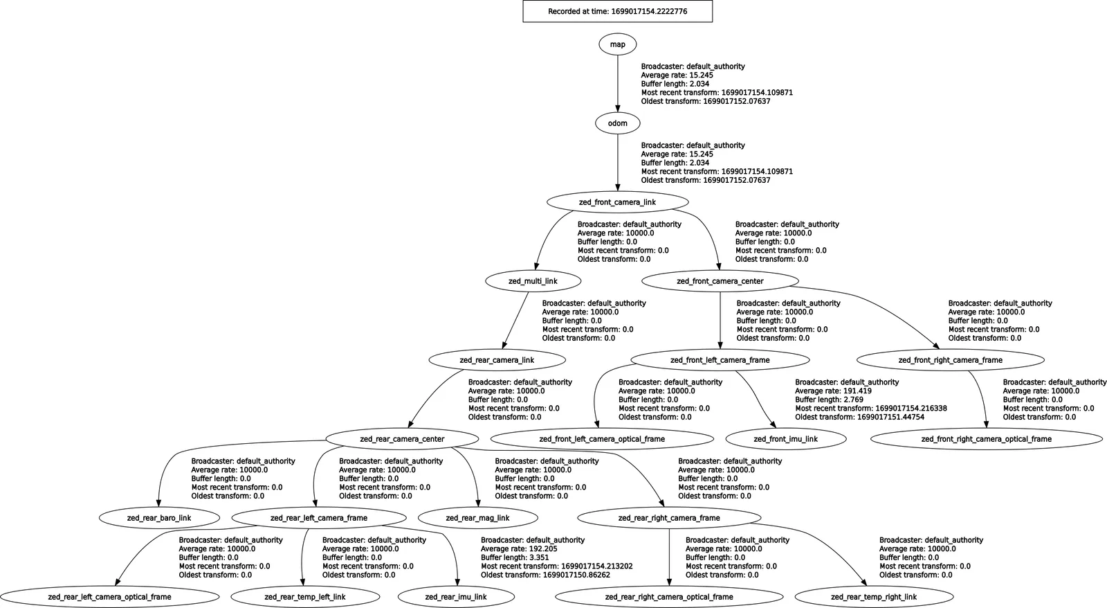
The following image displays the TF tree generated for the dual camera configuration of this tutorial:
You can retrieve the name of the container and check the components that are running in the same process by using the command
for example:
All the nodes run in the same namespace zed_multi.
Synchronized publishing of GMSL cameras
GMSL cameras connected to the same capture card capture their frames at the same instant. Since v5.6.0 of the ROS 2 Wrapper, they can also publish the same captures. It works with the stereo node (ZED X family) and the mono node (ZED X One family), also mixed in the same system. This matters when the publishing rate is lower than the grab rate (general.pub_frame_rate < general.grab_frame_rate), for example to reduce the load of a multi-camera robot.
By default, each ZED node selects the frames to publish with its own publishing timer. The timers of the different nodes are not related to each other, so two cameras that capture at the same instant usually publish frames captured one or more grab periods apart: with general.grab_frame_rate: 30 and general.pub_frame_rate: 10, the images published by two cameras can be 33 ms, 67 ms or more apart, and the gap can change while the nodes run.
With general.sync_pub_to_timestamp: true, each node selects the frames to publish on their image timestamp instead: time is divided into publishing periods (100 ms at 10 Hz) and the node publishes the first frame captured in each period. The synchronized cameras share the same capture timestamps, so all the nodes select the same frames, without any communication between them, and their images, depth maps and point clouds carry matching timestamps.
How to enable it
Set the parameter in the common_stereo.yaml file for the stereo cameras and in the common_mono.yaml file for the ZED X One cameras:
Requirements:
- The cameras must capture at the same instant: GMSL cameras connected to the same capture card.
- All the nodes must use the same
general.grab_frame_rateand the samegeneral.pub_frame_rate.
What changes when it is enabled
The mono node only changes how it selects the frames to publish. In the stereo node, which also computes the depth:
- The camera is grabbed at
general.grab_frame_rate:general.grab_compute_capping_fpsis ignored, with a warning at start-up if it is set. - The point cloud is published at
general.pub_frame_rate, together with the images:depth.point_cloud_freqis not used. - When the depth is only used for publishing, the node computes it only for the published frames, so the GPU load follows
general.pub_frame_rateinstead ofgeneral.grab_frame_rate. When a module needs the depth of every frame (Object Detection, Body Tracking, Spatial Mapping, or the positional tracking in a mode other thanGEN_3), the depth is computed for every frame as usual. - If the depth of the frame to publish is missing (for example, a frame was dropped), the node publishes the next frame and logs it: for that period only, the camera publishes one grab period later than the others.
In a test on an NVIDIA® Jetson AGX Orin™ (grab_frame_rate: 30, pub_frame_rate: 10) with three pairs of cameras (two ZED X Mini, two ZED X One GS, and a ZED X Mini with a ZED X One GS), the cameras published frames captured one grab period (33 ms) apart without synchronized publishing, or by chance the same captures, depending on when the nodes started. With sync_pub_to_timestamp: true, more than 99% of the published pairs came from the same capture in every combination.
Leave the parameter set to false (the default) for a single camera, or for cameras that do not capture at the same instant: it does not synchronize the capture of the cameras, it only makes the publishing follow it.