

Using the GPIOs on your ZED Box Mini and Mini Carrier Board
The ZED Box Mini and Mini Carrier Board expose 2 GPIOs (General Purpose Input/Output) that can be used for various purposes, such as controlling external devices or reading sensor data.
The GPIO pins are accessible via the GPIO header located on the right side of the ZED Box Mini and Mini Carrier Board.
A full description of the pinout is available in the Connectivity Guide.
- #03 - GPIO_11 [CMOS-3.3V]
- #04 - GPIO_12 [CMOS-3.3V]
GPIO_11 and GPIO_12 can be used as general-purpose I/O pins. They are 3.3V compliant and can be configured as either inputs or outputs.
Setup the device
If you purchased the ZED Box Mini or the Mini Carrier Board before October 2025, please upgrade your device by using the flash script available in the Flash your ZED Box Mini section of the documentation. This is required to enable the GPIO_11 and GPIO_12 pins.
Install the required software
To control the GPIO pins, you need to install the latest version of the libgpiod library from source, including its C++ and Python bindings. The version provided in the Ubuntu 22.04 repositories is outdated and does not include the necessary development files for building or running recent examples.
Add user to the gpio group
Add the current user to the gpio group to access the GPIO pins without using sudo:
Using the GPIO pins as input
When using the GPIO pins as inputs, you must connect either a pull-up or pull-down resistor to ensure reliable signal detection. A 470 Ω resistor has been validated for this purpose.
-
Pull-down resistor: Use a pull-down resistor to detect when the pin is connected to VCC (logic high).
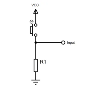
-
Pull-up resistor: Use a pull-up resistor to detect when the pin is connected to GND (logic low).
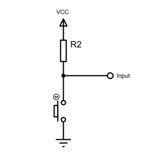
Without a pull-up or pull-down resistor, the input pin retains the set state (latch), without returning to the default state when the input voltage is removed. This can lead to unreliable readings.
Command Line Interface (CLI)
The libgpiod package includes command-line tools to interact with GPIO pins. The following examples demonstrate how to set and read the GPIO pins using these tools (libgpiod v2 syntax).
Set a pin HIGH. The command keeps the line set until you press Ctrl+C:
GPIO_11(PQ.06):gpioset -c gpiochip0 106=1GPIO_12(PN.01):gpioset -c gpiochip0 85=1
Set a pin LOW. The command keeps the line set until you press Ctrl+C:
GPIO_11(PQ.06):gpioset -c gpiochip0 106=0GPIO_12(PN.01):gpioset -c gpiochip0 85=0
Add the -z (--daemonize) option to run gpioset in the background and get the prompt back while the line keeps its value.
Read the GPIO level:
GPIO_11(PQ.06):gpioget -c gpiochip0 106GPIO_12(PN.01):gpioget -c gpiochip0 85
Read two values at the same time:
gpioget -c gpiochip0 106 85
If you added a Pull-Down resistor to the GPIO pin, you can use the VCC_3V3 pin (pin #07) of the GPIO header to stimulate the GPIO pins during the reading and verify their functionality in real-time.
If you added a Pull-Up resistor to the GPIO pin, you can use one GND pin (pin #2 or pin #8) of the GPIO header to stimulate the GPIO pins during the reading and verify their functionality in real-time.
You can find the full documentation of each CLI command on the official guide.
Python example
The following Python script demonstrates how to control and read the GPIO pins using the gpiod library. It toggles the state of GPIO_11 and GPIO_12 every second for 10 seconds, then reads their values for another 10 seconds.
If you added a Pull-Down resistor to the GPIO pin, you can use the VCC_3V3 pin (pin #07) of the GPIO header to stimulate the GPIO pins during the reading phase and verify their functionality in real-time.
If you added a Pull-Up resistor to the GPIO pin, you can use one GND pin (pin #2 or pin #8) of the GPIO header to stimulate the GPIO pins during the reading phase and verify their functionality in real-time.
The output will look like this:
The first line shows the GPIO chip information, the second line shows the status of the toggling operation, and the last line shows the read values of the GPIO pins. The information will update in place while the script is running.
You can find the full documentation of the Python binding API in the official guide.
C++ example
The following C++ program demonstrates how to control GPIO_11 and GPIO_12 using the gpiod library. It toggles the state of GPIO_11 and GPIO_12 every second for 10 seconds, then reads their values for another 10 seconds.
If you added a Pull-Down resistor to the GPIO pin, you can use the VCC_3V3 pin (pin #07) of the GPIO header to stimulate the GPIO pins during the reading phase and verify their functionality in real-time.
If you added a Pull-Up resistor to the GPIO pin, you can use one GND pin (pin #2 or pin #8) of the GPIO header to stimulate the GPIO pins during the reading phase and verify their functionality in real-time.
Build and Run
Create a file named test_gpio.cpp and copy the C++ code above into it. Then, compile the program using the following command:
Finally, you can run the example:
The output will look like this:
The first line shows the GPIO chip information, the second line shows the status of the toggling operation, and the last line shows the read values of the GPIO pins. The information will update in place while the script is running.
Other examples and more complex use cases can be found in the libgpiod Source Code repository.
You can find the full documentation of the C++ binding API in the official guide.
If you have any questions or need assistance with GPIO programming, please visit the StereoLabs Forums to connect with the community and get support from our experts.